Document information
Tags/Project: GERSEMI-wiki
| Metadata Field | Document Information |
|---|---|
| Status | Under Review |
| Created | 2026-06-23 |
| Last Updated | 2026-09-29 |
| Author | Davide Cuneo |
| Rev. # | 1.3 |
| Reviewers | Davide |
About the document
This document provides a description of the most important features of GERSEMI and the associated cryogenic system.
Technical Features and Specifications of GERSEMI
Introduction
The structural design of the GERSEMI vertical cryostat was primarily driven by two engineering prerequisites: geometrical volume constraints and multi-purpose operational versatility. Because the underground pit infrastructure had already been excavated during the initial construction of the FREIA Laboratory, the maximum external envelope of the cryostat was strictly bounded by the existing civil engineering dimensions.
Concurrently, as a university research facility, the system was required to maintain a high degree of adaptability to accommodate an extensive range of experimental equipment and testing configurations over its operational lifetime. This engineering trade-off resulted in a cryostat featuring an effective internal diameter of 1.1 m and an internal height of 4.7 m. This architectural envelope allows the integration of interchangeable structural inserts tailored to specific equipment requirements and thermodynamic test conditions:
-
Bath Insert: Configured for radio-frequency (RF) cavities or superconducting magnets that lack an integrated helium tank, allowing direct testing in a saturated liquid helium bath.
-
Lambda-Plate Insert: Engineered for testing superconducting magnets with a maximum stored energy of up to 340 kJ under pressurized helium conditions.
-
Vacuum Insert: Provisioned in the cryogenic system design for testing RF cavities or magnets enclosed within their own dedicated helium vessel, where the cold vessel of the cryostat functions directly as a vacuum vessel. While integrated into the plant design, this specific insert has not been constructed.
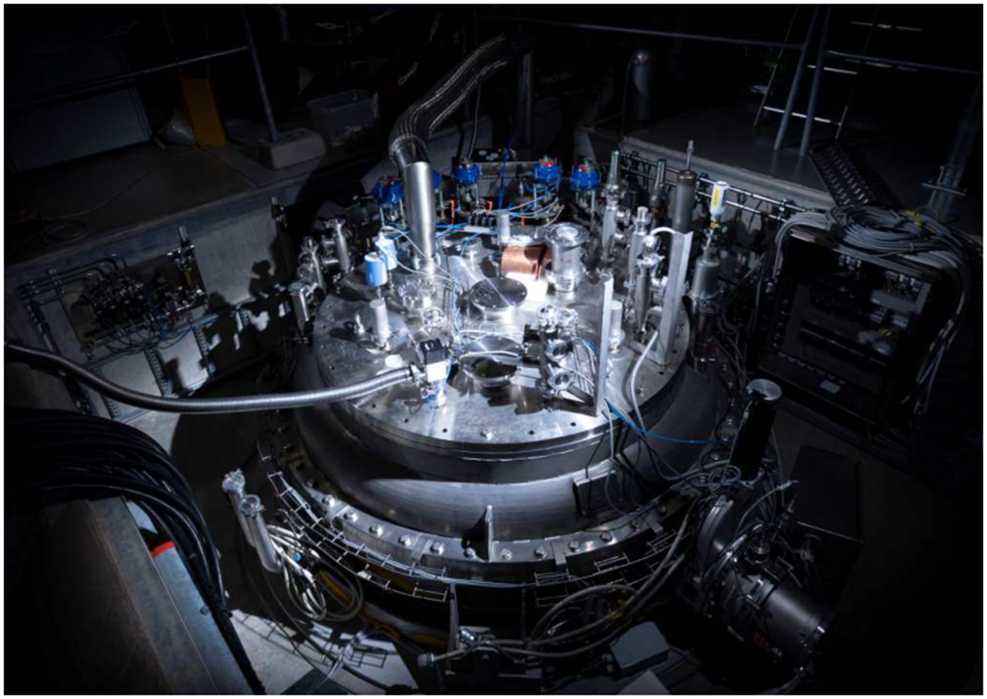
A famous artistic view of GERSEMI can be observed in Fig. 1.
System Main Parameters and Operational Boundaries
The GERSEMI vertical cryostat is engineered for high-precision characterization of superconducting cavities and magnets. The primary boundaries and operational ratings governing the system include:
| Parameter | Gersemi (vertical) |
|---|---|
| Purpose | Superconducting cavities and magnets |
| Size (for testing, below Lambda Plate) | 2.65 m height, |
| Achievable temperature | 1.1 m diameter |
| Pressure | 16 to 1250 mbar ( 0.1 mbar, measured at 16 mbar) |
| Cooling power | 90 W (at 1.8 K) |
| Allowed stored energy | Maximum 500 kJ |
| Allowed weight | Up to 5 ton |
Layout and Geometric Dimensions
The baseline mechanical dimensions of the primary facility equipment are summarized below:
| Equipment Component | Height [mm] | External Diameter [mm] |
|---|---|---|
| Cryostat: Vacuum Vessel | 4330 | 1960 |
| Cryostat: Pressure Vessel | 4770 | 1450 (Upper) / 1120 (Lower) |
| Reheater | 2970 | 800 |
| Valve Box | 2330 | 1016 |
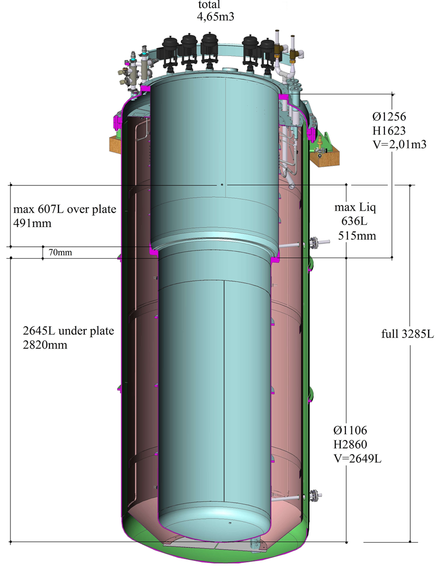
Fig. 3 shows a simplified model of the cryostat. The external vacuum vessel of the cryostat is manufactured from stainless steel, with an outer diameter of 1.8 m and an overall height of 4.7 m. The internal stainless-steel cold vessel features a stepped cylindrical geometry split into two functional sections: an upper section with a diameter of 1.25 m and a lower section with a diameter of 1.1 m. The structural step forming the transition seat between these two diameters serves as the mechanical sealing interface for the installation of the lambda plate, establishing the double-bath regime required for pressurized superfluid helium testing.
When configuring the facility for saturated liquid helium operations (cavity testing mode), thelambda plate insert is removed, and the liquid insert is deployed. Here, to minimize the total volume of liquid helium required to fill the vessel during these runs, displacement filling blocks manufactured from wood or Rohacell foam are inserted into the dead volumes.
Cryogenic system
The overall experimental setup comprises the vertical cryostat vacuum and pressure vessels, a cryogenic valve box acting as the distribution manifold to direct cryogens, and a dedicated reheater unit configured to warm the sub-atmospheric output helium gas before recovery. Each component will be described in a separate note for sake of completeness. The GERSEMI subsystem is integrated in series with a central L140 helium liquefier plant and a dedicated set of sub-atmospheric pumping trains. Mechanically, the facility is connected in parallel with the pre-existing HNOSS horizontal cryostat.
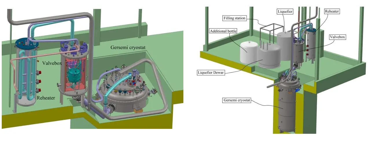
Fig. 2 shows an overall view of the integrated system. Because GERSEMI shares the sub-atmospheric pumping infrastructure with the HNOSS cryostat, it can access identical sub-atmospheric pumping regimes, enabling steady-state operations anywhere between 4.5 K and 1.8 K while maintaining its nominal 90 W cooling capacity at the 1.8 K limit. It is important to note that HNOSS and GERSEMI can not be operated in parallel due to the limitation of the cryogenic facility.
Static heat leaks due to conduction and radiation are managed through localized shielding and active cooling circuits. An aluminum thermal shield is installed around the main cold vessel and actively cooled via liquid nitrogen (LN2) circulation to suppress ambient radiation loads. Additionally, a supercritical helium circulation loop is routed around the neck of the cold vessel to intercept and limit conductive heat loads migrating downward from the warm top room-temperature flange.
The theoretical static thermal losses across the primary equipment components at different temperatures is defined as follows:
| Equipment Configuration | Thermal Load at 80 K | Thermal Load at 4 K | Thermal Load at 2 K |
|---|---|---|---|
| Valve Box | n.a. | 20 W | 4 W |
| Cryostat (Vacuum Insert mode) | 50 W | 2 W | 2 W |
| Cryostat (Bath Insert mode) | 200 W | 4 W | 4 W |
| Cryostat (Magnet Insert mode) | 150 W | 20 W | 17 W |
GERSEMI Operation Modes
There are three different operation modes that can be adopted by GERSEMI depending on the type of insert (we have two) that is used:
- Vacuum Mode (Conduction-Cooled / Dry Testing):
The magnet is housed within an evacuated vessel inside the cryostat rather than being immersed in liquid cryogens. Cooling is achieved via thermal conduction. - Liquid Bath Mode (Saturated Boiling Helium):
The magnet is directly immersed in a pool of saturated liquid helium. At standard atmospheric pressure, the bath boils steadily at . By engaging the facility’s sub-atmospheric pumping system, the internal pressure can be dropped (down to ), which lowers the helium boiling point and shifts the entire liquid bath down to a saturated superfluid state at . - Pressurized Bath Mode (Subcooled Superfluid via 2K Heat Exchanger):
Physics of liquid helium and Pressurized Bath Mode for dummies
At atmospheric pressure (), liquid helium exists as a normal, boiling fluid known as Helium I at a temperature of . However, if it is cooled down further to (a specific thermodynamic boundary known as the Lambda Point, ), helium undergoes a second-order phase transition.
Below , it transforms into Helium II (Superfluid Helium). In this state, the fluid exhibits quantum macroscopic properties:
- Zero Viscosity: It can flow through microscopic capillaries without friction.
- Higher Thermal Conductivity: Its effective thermal conductivity spikes to thousands of times that of solid copper. Instead of propagating heat via slow, standard molecular diffusion, Helium II moves heat via thermal wave propagation (known as “Second Sound”) almost at the speed of sound, instantly equalizing temperatures across the bath.
While a standard Liquid Bath mode achieves by lowering the entire cryostat’s pressure to (forcing the liquid into continuous, volatile boiling), the Pressurized Bath Mode isolates temperature from pressure using the Lambda Plate and the 2K Heat Exchanger.
- The Upper Reservoir (Helium I): The section above the Lambda Plate stays open to the atmosphere (), remaining as normal boiling liquid helium at . It acts as a thermal blanket and a fluid makeup reservoir.
- The Sealed Lower Sub-Plate (Helium II): The lower section containing your magnet is hydraulically sealed by the Lambda Plate. It is maintained at a full 1 bar of pressure but its temperature is actively driven down to .
Operating the magnet in a subcooled, pressurized superfluid bath rather than a standard boiling bath yields two vital benefits:
- Total Suppression of Boiling: Because the lower bath is at , it would need to reach to boil. At , any heat dissipated by the magnet’s ramps or joints merely warms the surrounding liquid locally (e.g., to ) without creating vapor bubbles. This ensures the superconduting cables remain 100% in contact with liquid.
- Instantaneous Thermal Dissipation: Thanks to the infinite thermal conductivity of Helium II, localized hot spots or energy micro-releases from the magnet are instantly swept away.
Feedback
Found an error or something outdated in this note? Please contact Davide Cuneo (davide.cuneo@physics.uu.se).