Document information
Tags/Project: GERSEMI-wiki
| Metadata Field | Document Information |
|---|---|
| Status | Under Review |
| Created | 2026-06-24 |
| Last Updated | 2026-09-29 |
| Author | Davide Cuneo |
| Rev. # | 1.3 |
| Reviewers | Davide |
About the document
This document provides a description of the multiple inserts that can be used within the GERSEMI cryostat
Geometrical Boundaries
The GERSEMI vertical cryostat utilizes interchangeable structural inserts suspended from the top flange to match specific experimental scenarios. The internal stainless-steel pressure vessel features a stepped cylinder design that dictates the available spatial envelopes:
- Upper Section Envelope: Internal diameter .
- Lower Section Envelope: Internal diameter .
When configuring the cryostat without the lambda plate assembly, the central structural boundary is completely removed. This opens the entire internal volume of the vessel, eliminating the 70 mm structural transition zone and the physical thickness of the plate. This modification extends the continuous vertical testing envelope by 465 mm of useful height, increasing the total liquid helium capacity from 2645 liters (under-plate volume) to 3285 liters, which yields a net volume gain of 640 liters.
Magnet Insert
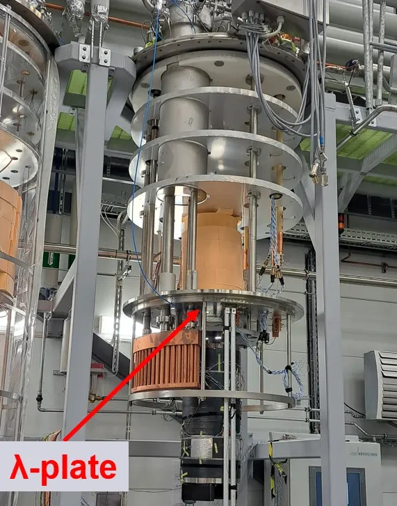
The Magnet insert is the most complex configuration in terms of mechanical, electrical, and cryogenic design, following the general architectural baseline developed at CERN for high-current magnet testing. It is engineered to operate between 4.2 K and 1.9 K by maintaining the sub-cooled liquid helium bath at a pressure slightly above atmospheric (pressurized He-II state), and its safety systems are rated to handle the rapid dissipation of the energy stored in the magnet during a quench. Because the operating pressure of this insert fluctuates between 1 bar and 5 bar, the top flange features a specialized structurally bulged design. The maximum allowable length for the magnets under test is strictly limited to 2.2 m.
Mechanical Sealing and Thermal Shielding
The separation between the 4 K upper bath and the 1.8 K lower bath relies on a lambda plate manufactured from 316L stainless steel with a thickness of 64 mm. The plate seats directly on the internal rim where the pressure vessel changes diameter. The primary thermodynamic seal is secured by the structural weight of the suspended magnet hanging directly from the plate. To ensure the integrity of the seal between the two baths, both the landing seat and the lambda plate are machined to a flatness tolerance of at least 0.1 mm.
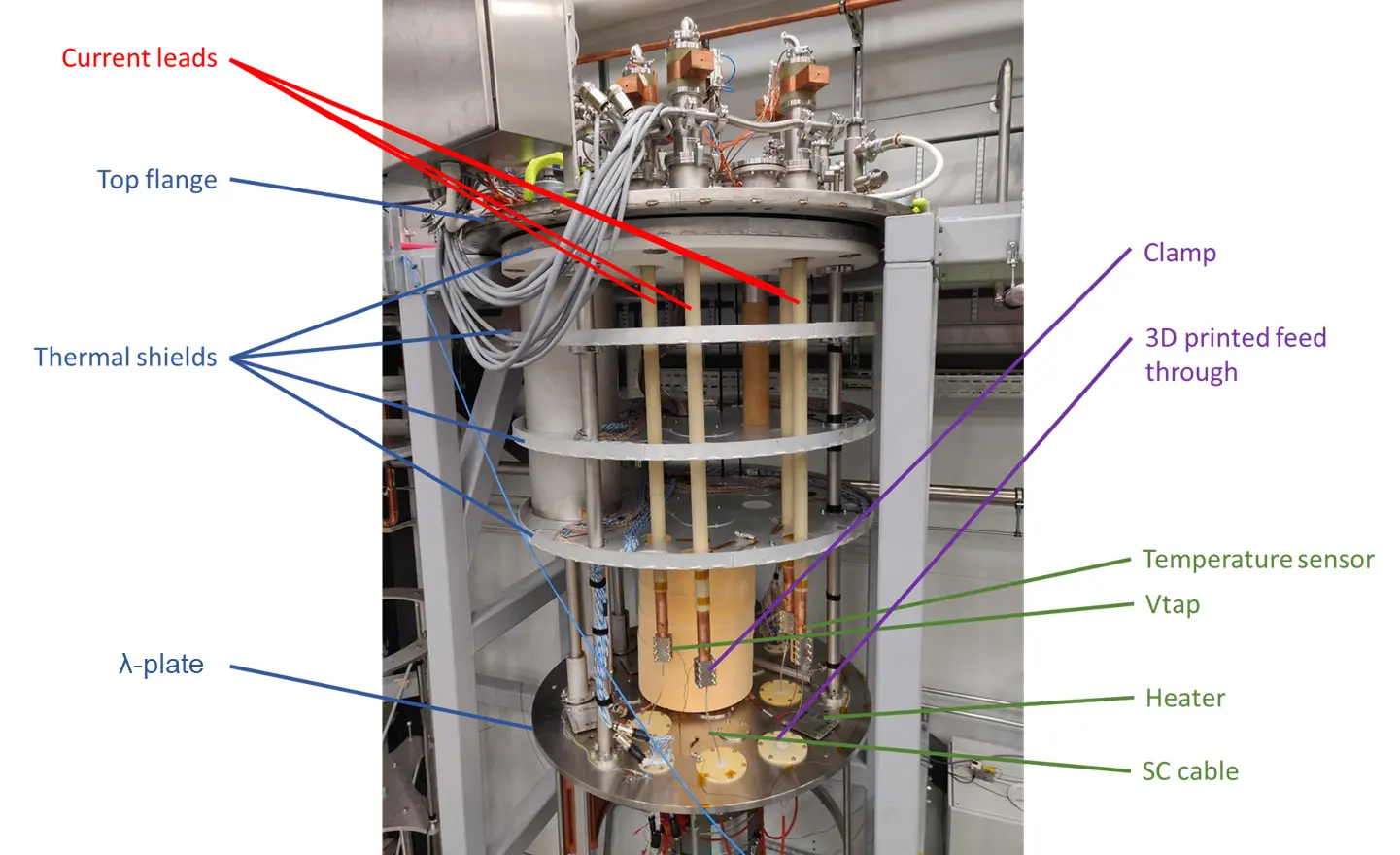
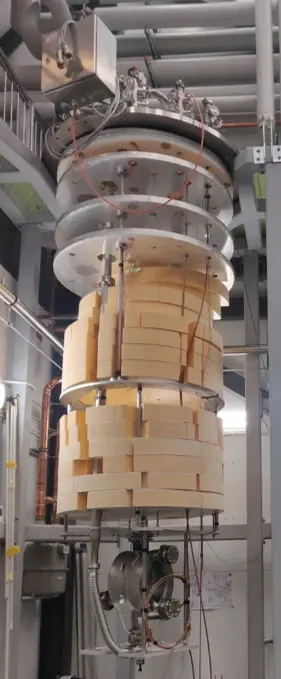
To minimize parasitic heat leaks migrating from the warm top flange toward the liquid baths, the upper section of the insert is equipped with flat, non-actively cooled aluminum thermal plates stacked vertically below one another. Acquisition signals, instrumentation lines, and process piping are thermally anchored to these screens as they route toward the top flange.
High-Current Powering and Splicing Clamps
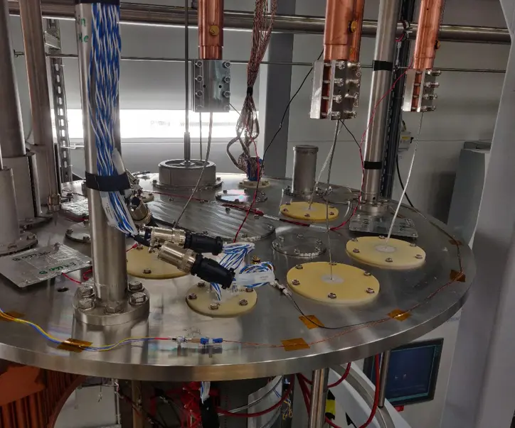
Electrical power is delivered to the magnet through up to four vapor-cooled current leads rated for a maximum current of 2 kA DC each. These leads penetrate the top plate and pass vertically through the lambda plate via feedthroughs sealed with cryogenic-grade Stycast epoxy resin.
To bridge the current lines from the leads to the magnet terminals, a specialized mechanical clamping system is deployed, acting as the structural electrical interface between the current lead and the superconducting (SC) cable above the lambda plate, and between adjacent SC cables below the plate. The connection between the copper bus bar and SC cable and SC cable and magnet end is done through specifically designed stainless steel clamps. Here, for the SC cable a dedicated groove with its shape was machined. The contact resistance is reduced using indium wire.
Sub-Cooling Components and Safety Loops
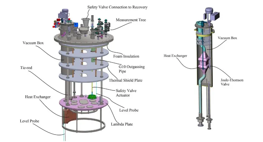
The sub-cooling loops and associated instrumentation are distributed both above and below the lambda plate partition. Initial operation requires filling the pressure vessel from the bottom with liquid helium at 4 K. Continuous cooling of the lower bath is achieved via a high-surface copper heat exchanger located below the lambda plate, featuring an internal pipe surface area of 1 and a nominal cooling power of 120 W at 1.8 K. This unit operates in series with an auxiliary counterflow heat exchanger and a Joule-Thomson expansion valve located above the lambda plate, which are housed inside a separate vacuum box (anticryostat). The low-pressure exhaust of this internal heat exchanger loop is tied directly to the facility’s external sub-atmospheric pumping trains. Subsequent replenishment of the lower 1.8 K bath is regulated via a dedicated valve linking the two fluid volumes.
The top flange contains dedicated ports for all process instrumentation alongside an extra transfer line configured to manage and vent outgassed helium from the upper 4 K bath. System overpressure protection is managed by an integrated safety loop: in the event of a sudden pressure build-up in the lower bath (e.g., during a magnet quench), a safety valve passing through the lambda plate opens, releasing the sub-cooled fluid into the upper 4 K bath volume. This pressure spike is then mitigated by the buffer volume above the plate and exhausted safely through an independent primary safety valve installed on the bulged top flange. A schematic with the details of the insert and the described separate assembly for the subcooling is shown in Fig. 3.
The Bath Insert
The bath insert represents the simplest mechanical configuration and is utilized to test radio-frequency (RF) cavities. Depending on the physical dimensions of the hardware under test, the internal volume of GERSEMI can accommodate either one or two cavities simultaneously.
The structural load of the cavities is suspended from a cavity support plate, which is secured to vertical tie-rods fastened directly to the main top flange of the insert. To suppress vertical radiant heat leaks into the liquid bath, a series of flat aluminum thermal screens (not actively cooled) are stacked horizontally below the top flange. All process piping connecting the top flange to the cavities is thermally anchored to these plates.
During standard operation, the initial filling of the bath is executed from the bottom of the pressure vessel, while subsequent refills are routed through a dedicated side port located above the lambda plate landing seat. All process instrumentation required for monitoring and controlling the cavities and the helium mass flow—including electrical heaters, temperature sensors, level probes, pressure gauges, and beam vacuum connections—is routed through dedicated feedthrough interfaces built into the top flange assembly.

Feedback
Found an error or something outdated in this note? Please contact Davide Cuneo (davide.cuneo@physics.uu.se).