Document information
Project: GERSEMI-wiki]
| Metadata Field | Document Information |
|---|---|
| Status | Under Review |
| Created | 2026-06-21 |
| Last Updated | 2026-09-29 |
| Author | Davide Cuneo |
| Rev. # | 1.3 |
| Reviewers | Davide, Rocio |
Introduction and Context
This technical document provides the operational framework and structural overview of the testing infrastructure utilized within the FREIA Laboratory. The main objective is to establish a comprehensive reference guide for the integration, cooling, and operational management of advanced superconducting magnet inserts within the vertical cryostat testing facility. The specific configurations and instrumentation nomenclature detailed herein correspond directly to the control room monitoring interface of the GERSEMI system.
Interface Quick Reference Guide (Colors and Nomenclature)
This section provides the reference framework for interpreting the symbols, tag nomenclature, and color coding used in the GERSEMI Magnet Insert and cryogenic system control diagram. The interface layout corresponds to the control room monitoring system located in the basement of the FREIA laboratory.
Color Coding Conventions
Colors within the diagram designate process fluids, mechanical boundaries, or component states.
| Color | Applied Meaning / Process Fluid | Operational Context |
|---|---|---|
| Light Blue | Liquid Helium (LHe) line | Main cooling loop distribution. |
| Orange | Liquid Nitrogen (LN2) line | Thermal shield cooling circuits. |
| Brown | Lambda Plate (-plate) | Geometric and thermal boundary definition. |
| Black | Fluid pipelines / Structural edges / Current leads | Identifies generic piping, cryogenic box boundaries, and the four main electrical current leads. |
| Grey | Containment volumes / Indicator backgrounds | Differentiates physical volumes and provides the background for sensor reading fields. |
| Dark Green | System Indicators (OFF State) | Represents the deactivated or closed state on the control panel. |
| Light Green | Liquid helium?? | Ask Rocio again |
Instrumentation Coding (ISA-5.1 Standard)
The tag nomenclature implemented in the system diagram complies with the ISA-5.1 (Instrumentation Symbols and Identification) international standard. Each instrument identifier consists of a combination of letters where the first letter designates the measured or initiating variable, and the succeeding letters define the component’s specific function.
| Letter | First Letter Meaning | Succeeding Letter Meaning | Diagram Examples |
|---|---|---|---|
| C | — | Controller | CV680, LIC683 |
| E | Electricity / Heating Element | — | EH680 (Electrical Heater) |
| F | Flow Rate | — | FV680, FV080 |
| H | — | Hand / Manual Operation | — |
| I | — | Indicator | PI060M, LI683 |
| L | Level | — | LT, LIC683 |
| P | Pressure / Vacuum | — | PI060M, PT661M |
| T | Temperature | Transmitter | TT (Temperature Transmitter / CERNOX) |
| V | — | Valve | CV680, FV680 |
Component and Symbol Inventory
This chapter catalogs the graphical symbols used in the GERSEMI control interface to represent physical instrumentation and cryogenic components. Pressure and level sensors do not have dedicated graphical symbols and are identified solely by their alphanumeric tags.
| Component | Coding | Symbol | Description |
|---|---|---|---|
| Electrical Heater | EH |  | Film-based heating element. Four units surround the magnet assembly to facilitate warm-up procedures following a quench event. |
| Analog/Hand Valve | HV |  | Continuously adjustable valve for fluid flow regulation. |
| Flow electric Valve | FV |  | Actuated valve utilizing an electric motor or solenoid for open/close operations. |
| Electric Valve (Variable Section) | CV |  | Actuated valve designed with a variable cross-section for precise throttling or modulating control. These valves could be controlled directly due to other sensors |
| Heat Exchanger | HX |  | Passive thermal management component utilized for fluid pre-cooling or sub-cooling processes. |
| Temperature Sensor | TT |  | CERNOX resistance thermometer deployed for localized thermal monitoring across the insert. |
| Containment Tank | — |  | Pressurized or atmospheric storage volume for cryogenic fluids. |
| Pressure sensor | PI or PT |  | Sensor used to monitor pressure |
| Flow rate sensor | FT |  | Sensor used to monitor fluid volumetric or mass flow rate within the process lines. |
| Control Loop Assembly | FIC / LIC | 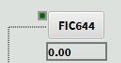 | Control loop sub-assembly consisting of a loop status indicator (green square)and an alphanumeric tag box with its process value display |
System Hardware and Component Architecture
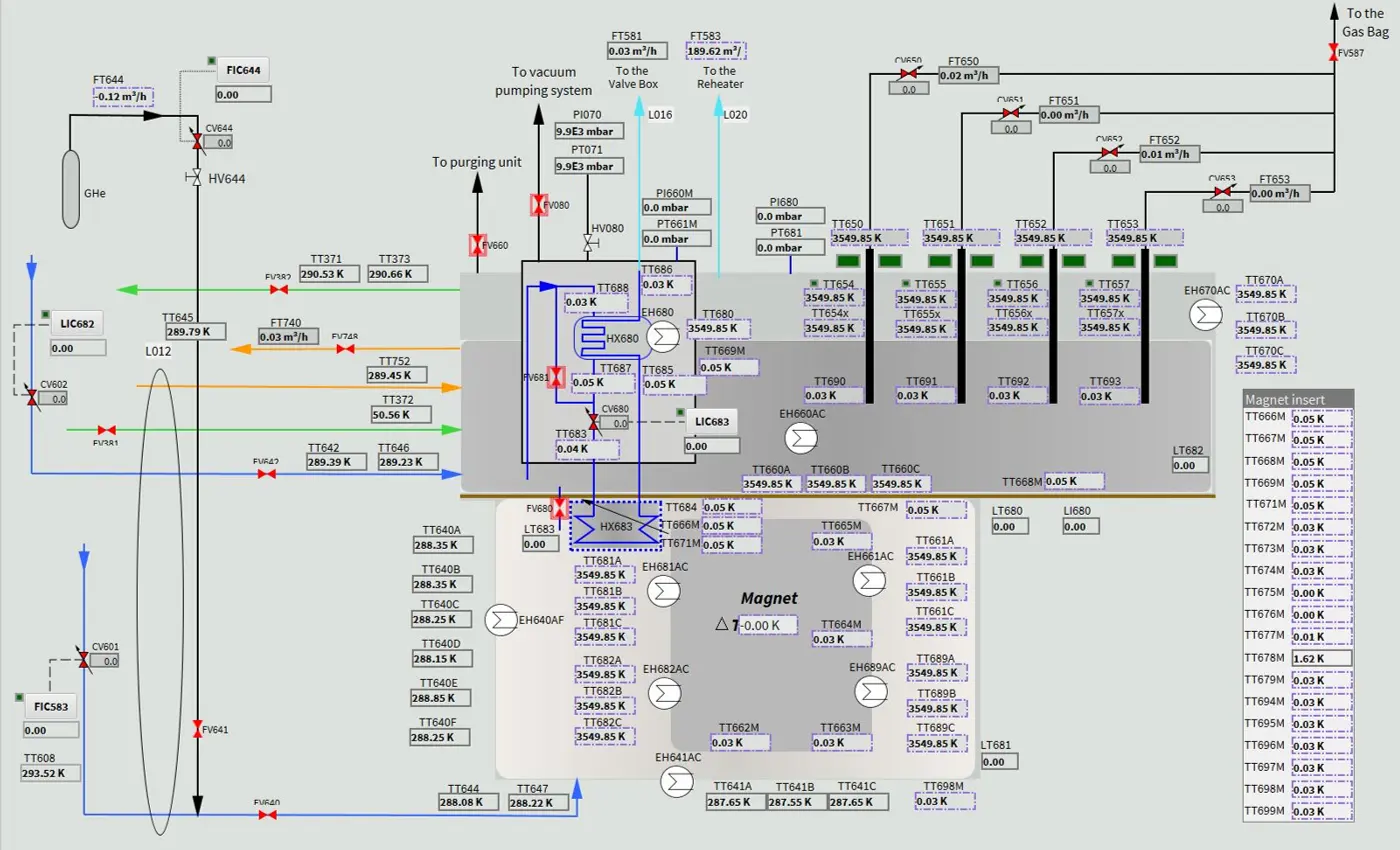
The picture below illustrates the GERSEMI Magnet Insert and cryogenic system control diagram. It will be the reference for the description of the operating principles as well as the main interface adopted during the testing phase.
Macroscopic Description of the Layout
The GERSEMI cryostat is installed in an underground cavity that defines the external geometrical boundaries of the system. The hardware consists of two primary concentric assemblies:
- the stationary vertical cryostat vessel, GERSEMI
- the removable magnet insert suspended within it.
Before operations, to mitigate thermal convection from the ambient environment to the inner cryogenic zones, the air volume within the outer cavern and the surrounding boundaries is evacuated to establish a high-grade insulation vacuum. Under these conditions, heat transfer is restricted exclusively to thermal radiation.
Thermal Shield and LN2 Piping
An aluminum thermal shield cylinder is positioned concentrically inside the vacuum space to intercept the ambient radiant heat load acting on the liquid helium vessel. This thermal shield is actively cooled by a network of liquid nitrogen (LN2) pipelines, represented by the orange process lines.
Remember that the material of the thermal shield must have a HIGH thermal conductivity. Even if it seems counterintuitive their objective is to lead heat as fast as possible to the cooling channels (in this case the LN 2 serpentine welded on the cylinder) and not to let the heat deposited somewhere.
Because the radiation load varies geometrically between the vertical boundaries of the cylinder and the upper entry plates, the piping is split into two independent circuits. The lateral circuit is welded directly to the vertical walls of the cylinder to handle radial loads, while a dedicated top circuit cools the upper section of the shield to prevent thermal gradients across the internal volume.
LHe Vessel and Lambda Plate
The innermost section of the cryostat houses the liquid helium (LHe) containment vessel, which is physically and thermodynamically divided by a thick horizontal lambda () plate, represented by the brown rectangle. This structural plate separates the main volume into two operational regimes.
The lower volume below the lambda plate remains sealed during steady-state operations, while the upper volume functions as a low-pressure buffer. Unidirectional fluid communication between these two zones is controlled via a bypass line equipped with valve FV680. The fluid mass and head profile inside the overall vessel are monitored by four distributed level transmitters (LT683, LT680, LT681, and LT682).
Superconducting Magnet and Current Leads
In the diagram, the superconducting magnet assembly is located inside the lower gray box boundary below the lambda plate. In the practical application the magnet will be suspended by mechanical supports specifically designed to sustain the structural weight depending on the application. Therefore, here on the diagram this supports are not shown. The magnet assembly is surrounded by four integrated electrical quench heaters used to rapidly warm the coil mass during quench for protection.
Power is delivered to the windings via four current leads (black rectangles) penetrating the top plate. These leads extend through the upper vessel and are partially submerged in the liquid helium bath. They operate at approximately 20 K using vapor cooling.
Instrumentation on each current lead consists of three CERNOX temperature sensors: two positioned in the gas phase above the liquid level and one in the submerged section. An additional array of four CERNOX sensors is installed immediately above the lambda plate at the physical electrical joints connecting the current leads to the magnet terminals. Each lead features a dedicated gas exhaust circuit routed to the facility Gas Bag to collect evaporated helium for future purification.
Sub-Cooling system
The sub-cooling loop is an independent unit operation contained within the solid black rectangular boundary located above the lambda plate, designed to drive the phase transition from normal helium (He-I) to superfluid helium (He-II). The hardware loop consists of the primary convective heat exchanger HX680, which pre-cools the incoming liquid by transferring heat to the returning cold process vapors.
Downstream of HX680, the pre-cooled fluid is routed to the Joule-Thomson expansion valve CV680, which is actively modulated by the level controller LIC683. The sub-cooled liquid then passes through the lambda plate into the submersed heat exchanger HX683, located inside the lower vessel to thermalize the magnet environment.
The vapor return path from the sub-cooling stage travels back upward through the right side of the circuit, passing an inline electrical heater EH680 before exiting the cryostat boundaries toward the external Valve Box manifold. Finally, the facility integrates an independent purging unit connected to the main lines to handle initial vessel evacuation and pure helium backfilling.
Description of the system operations
Initial Conditioning and Vacuum Insulation
Info
Rocio comments on this since I think I am missing something
The operational cycle begins with the deployment of the purging unit to isolate the inner process volumes from the atmosphere. This system evacuates the main liquid helium vessel and associated pipelines, subsequently backfilling them with pure helium gas at 1 bar. This conditioning step removes residual atmospheric air and moisture, preventing localized ice blockages or freezing within the narrow pipeline networks during subsequent cooling stages. Concurrently, the external pumping systems evacuate the empty volume within the underground vault surrounding the aluminum thermal shield. Establishing this high-grade insulation vacuum suppresses convective thermal loads, isolating the internal cryostat boundaries so that radiation remains the only active heat transfer mechanism from the room-temperature environment.
Thermal Shield Activation and Pre-Cooling
Because the extreme temperature gradient between room temperature (~300 K) and liquid helium (~4.5 K) would trigger immediate, uncontrollable flash evaporation of the primary cryogen, an intermediate thermal barrier must be established before handling helium. Liquid nitrogen (LN2) is injected into the orange process lines welded to the outer surface of the aluminum thermal shield. As the shield thermalizes toward 77 K, it intercepts the ambient radiant heat load, lowering the background temperature profile seen by the inner liquid helium vessel. To ensure uniform temperature distribution, the lateral circuit stabilizes the vertical walls of the shield cylinder, while the independent top circuit actively cools the upper boundary zone to counteract the non-uniform radiation loads entering from the top plate.
Cryostat Filling
Info
The way I am describing the cooling of CLs is correct?
Once the radiation shield reaches steady-state operation, the primary filling process begins via the blue lines. Liquid helium at approximately 4.5 K is injected from the bottom of the cryostat into the lower vessel volume. Due to the initial temperature differential between the warm vessel structures and the cryogenic fluid, a substantial portion of the helium flashes into gas, absorbing the sensible heat of the metal mass and thermalizing the lower box. Once this lower zone is stable, the bypass valve FV680 on the left side of the lambda plate is opened. Liquid helium then flows upward through the manifold, filling the upper volume to a designated height submerging partially the current leads, represented by the four black rectangles. The cold helium gas evaporating from this bath routes upward through the four current lead branches, cooling them to an operational threshold of roughly 20 K before exiting into the facility Gas Bag.
Pumping Loop and Superfluid Transition (He-II)
Info
Did I described the process correctly?
If one want to achieve the sub-cooled state to operate at 1.9 K, the liquid helium bath must transition from normal fluid (He-I) to superfluid (He-II). Liquid helium is continuously drawn from the upper buffer volume above the lambda plate (through the left-side blue line) and fed into the (black) sub-cooling assembly. The fluid first circulates through the primary heat exchanger HX680, undergoing convective pre-cooling against the cold, low-pressure vapors returning from the lower stages. The pre-cooled liquid then reaches the Joule-Thomson expansion valve CV680, which is actively modulated by the level controller LIC683.
The mechanism driving the temperature drop is a external sub-atmospheric pumping system connected via valve FV080 and monitored by pressure indicators PI060M and PT661M. By evacuating the vapor above the liquid inside the sub-assembly, these pumps lower the saturated vapor pressure from 1 bar down to approximately 23 mbar. When the pre-cooled helium passes through CV680 into this low-pressure zone, it undergoes rapid expansion and partial flash evaporation, absorbing latent heat and driving the remaining liquid temperature past the lambda point down to 1.9 K.
This sub-cooled superfluid helium is routed down through the lambda plate into the submerged heat exchanger HX683, where it continuously extracts heat from the lower vessel to thermalize the lower bath. While the inside of the sub-cooling loop operates at 23 mbar, the main lower vessel housing the magnet remains sealed at an atmospheric pressure of 1 bar. This spatial separation creates pressurized superfluid helium (He-II) around the magnet. Finally, the evaporated helium vapors travel back upward through the right side of the circuit, passing the electrical conditioning heater EH680 before exiting toward the external Valve Box manifold, which routes the cold residual gas back into the laboratory purification system to close the recovery loop.
Feedback
Found an error or something outdated in this note? Please contact Davide Cuneo (davide.cuneo@physics.uu.se).