Document information
Tags/Project: Operational-Notes-wiki
| Metadata Field | Document Information |
|---|---|
| Status | Draft |
| Created | 2026-09-24 |
| Last Updated | 2026-09-29 |
| Author | Davide Cuneo |
| Rev. # | 0.5 |
| Reviewers | TBD |
Source documents. This note combines the notes taken by the author at SM18 (CERN) during the explanations of Jérôme and Jean Luc Guyon with the CERN document PotAim card description. Figures marked “original” come from that document.
Introduction and Context
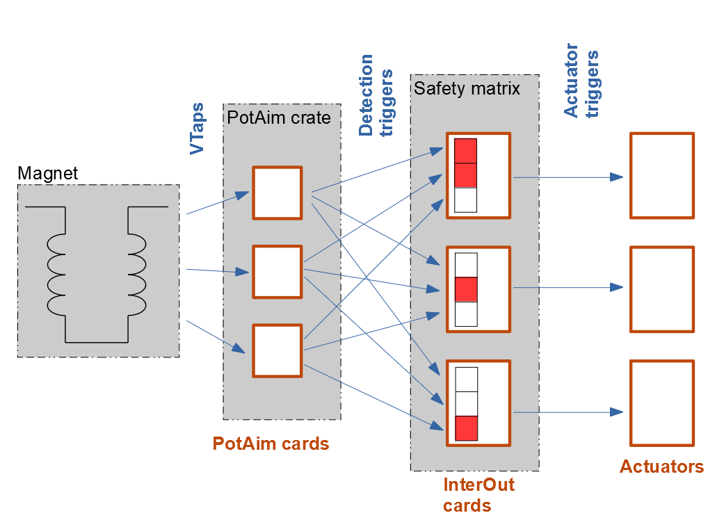
The PotAim system is the first element of the magnet protection chain. Its purpose is to detect quenches from the voltages measured between connections placed on different parts of the superconductor, the Voltage Taps (VTs or Vtaps).
Each PotAim card has two functions:
- Protection. It compares the measured voltages with the thresholds set on the card and, if a threshold is exceeded for long enough, generates a trigger. The trigger is routed to the Safety Matrix, which fires the protection actuators (fast abort of the power converters, energy extraction, quench heaters, etc.).
- Measurement. It amplifies the input voltages and provides them, isolated, to the DAQ system for the subsequent analysis.
This note describes the PotAim crate and card, how the card is configured, and gives the practical guidelines, learnt at SM18, to choose mode, gain, threshold and validation time depending on the signal to be protected.
The PotAim System in the Protection Chain
The system consists of PotAim cards placed in PotAim crates. A crate contains up to 10 independent cards. Each card has two channels (A and B), which generate a common trigger from two independent Vtap measurements: one PotAim card, one trigger. The triggers are connected to the Safety Matrix, which triggers the protection actuators accordingly.
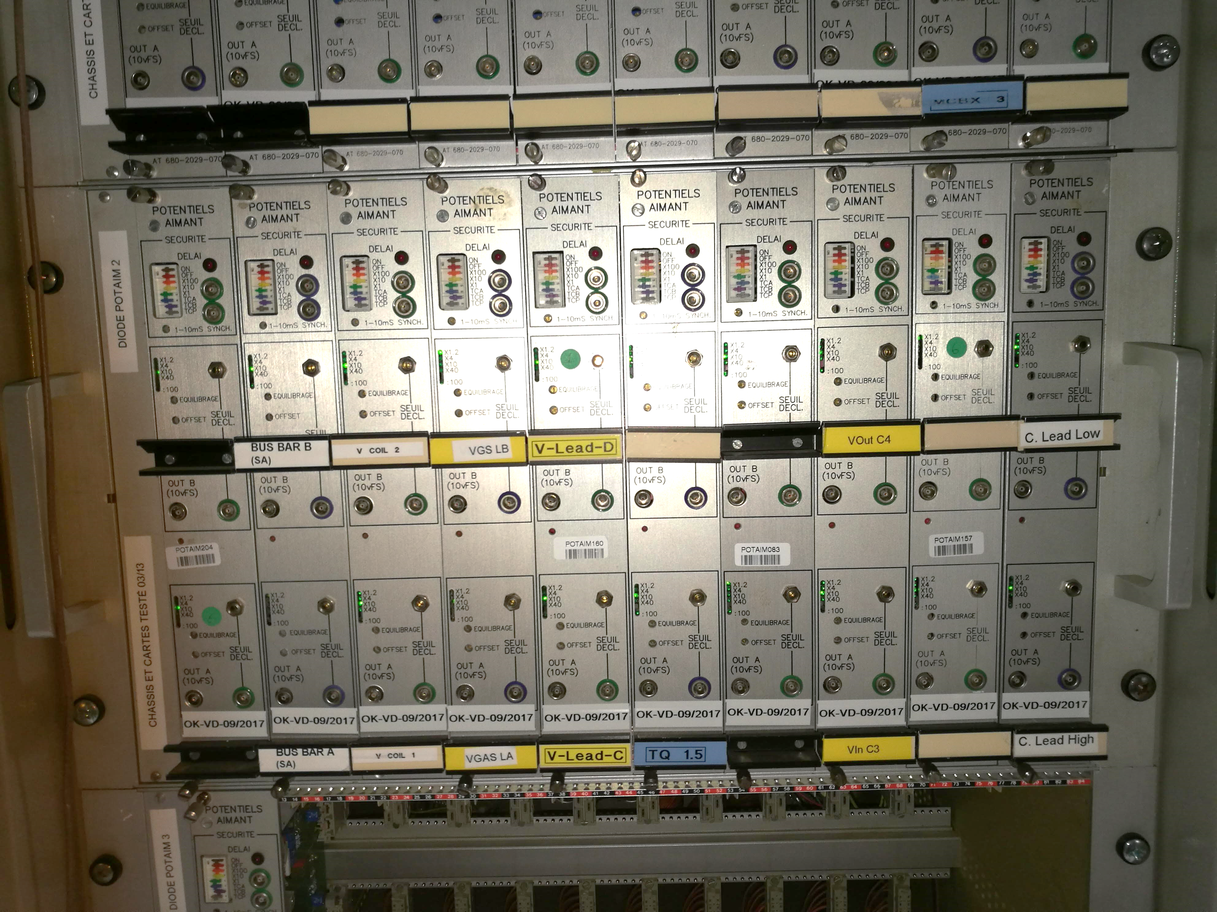
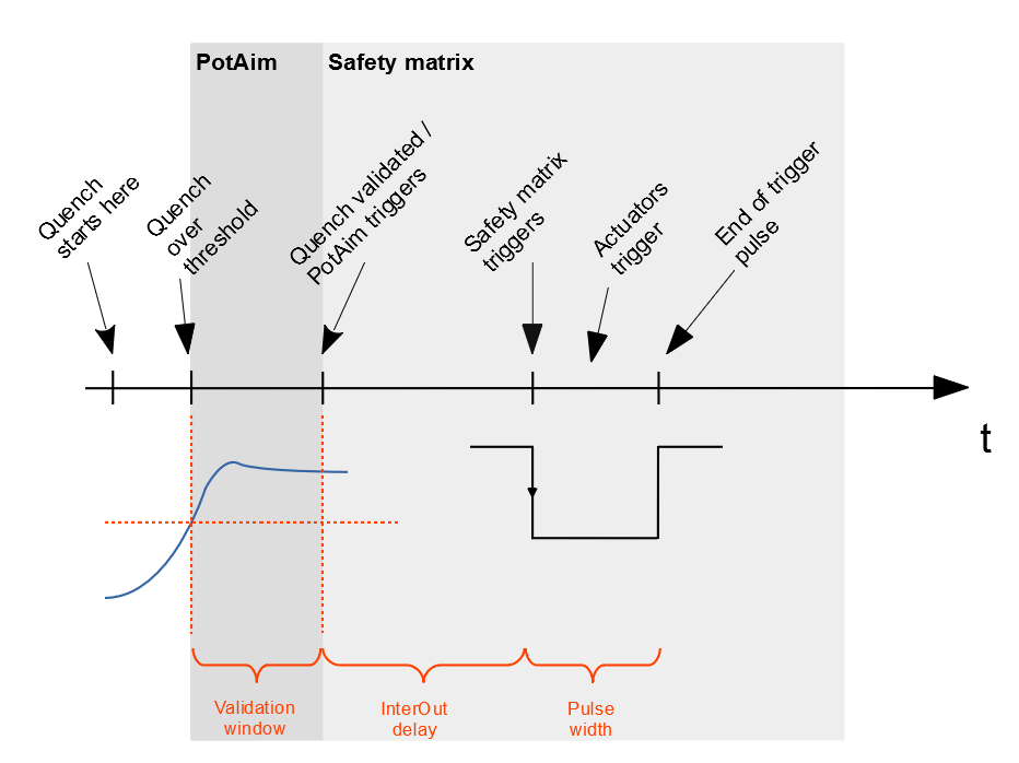
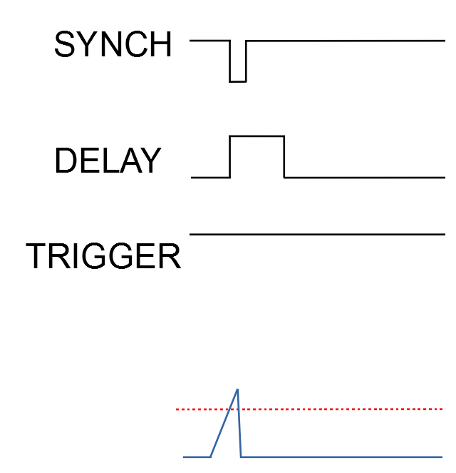
The time sequence of a protection event is shown in Figure 3. The PotAim is responsible for the first part: the voltage crosses the threshold, the validation window starts, and only if the voltage stays above the threshold until the end of the window the quench is validated and the trigger is sent. The Safety Matrix then adds its own delay and triggers the actuators.
The PotAim Crate
Crate connectors
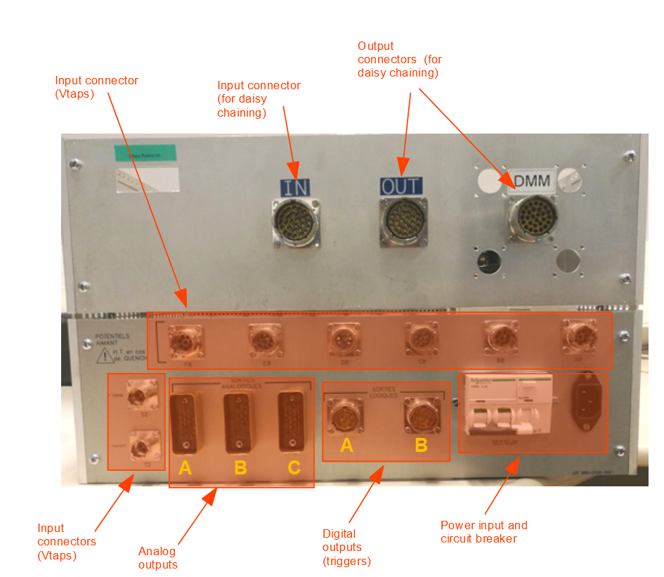
All the input and output connectors of the crate are at the back (Figure 4).
| Connector | Type | Function |
|---|---|---|
| Vtap inputs | Burndy 8 and Burndy 4 | Direct connection to the cryostat connector block (Fischer connectors). The 4-pin connectors are used for the current leads, the 8-pin ones for the rest. |
| Daisy-chaining input (IN) and output (OUT) | Burndy 28 | Connection of several crates one after the other. For the first chassis it is used to route the signals to the DMM |
| Analog outputs A, B, C | — | Isolated analog signals of the cards, to the DAQ. |
| Digital outputs A, B | — | Trigger signals, to the Safety Matrix. |
| Power input | — | Power supply of the crate, with circuit breaker. |
The Vtap input and the daisy-chaining connectors do not have fixed connections: they can be customised. With prepared cables, each input signal can be connected to the internal connection block (i.e. to the inputs of a PotAim card) or to the output connectors, to propagate it to cards in other crates.
High voltage on the input side
During a quench, the signals in direct contact with the magnet can reach high voltages. For this reason each PotAim card has an isolated input stage. The output signals can be connected to the rest of the instrumentation, whereas the input signals and connectors (Vtap inputs and daisy chaining) can carry high voltage and must be handled carefully, well insulated from other equipment.
Internal cabling
Inside the crate there is an internal connection block (Figure 5). With small cables, each input signal coming from the Burndy 4, 8 or 28 connectors can be connected to any input channel of any PotAim card. The figure also shows 468 Ω series resistors between the connection block and the high voltage connectors of the cards.
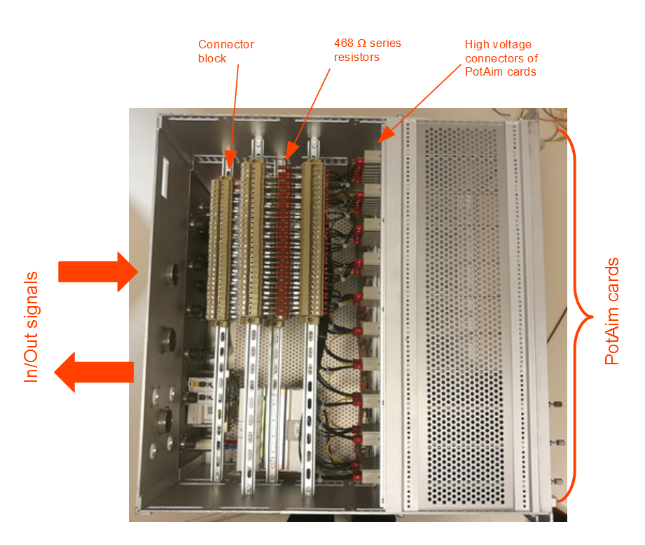
Each card uses six terminals of the block, three per channel (positive, negative, middle), in order:
Table 1: Terminals of the internal connection block.
| Terminal | Card | Channel | Input |
|---|---|---|---|
| 1 | 1 | A | Positive |
| 2 | 1 | A | Negative |
| 3 | 1 | A | Middle |
| 4 | 1 | B | Positive |
| 5 | 1 | B | Negative |
| 6 | 1 | B | Middle |
| 7 | 2 | A | Positive |
| 8 | 2 | A | Negative |
| 9 | 2 | A | Middle |
| … | … | … | … |
| 58 | 10 | B | Positive |
| 59 | 10 | B | Negative |
| 60 | 10 | B | Middle |
In general, card n uses terminals 6(n−1)+1 to 6(n−1)+3 for channel A and 6(n−1)+4 to 6n for channel B.
The PotAim Card
Basic functionality
Each channel of the card performs two functions (Figure 6):
- Window detector. The input signal is compared with a symmetric threshold, positive and negative. A detection signal is generated only if the signal stays above the threshold, in absolute value, for the whole validation time.
- Analog front-end. The card works as an analog front-end for the DAQ. It provides over 1 kV of isolation between the magnet and the instrumentation racks, and filters the input signal with a first-order filter with a 600 Hz cut-off.
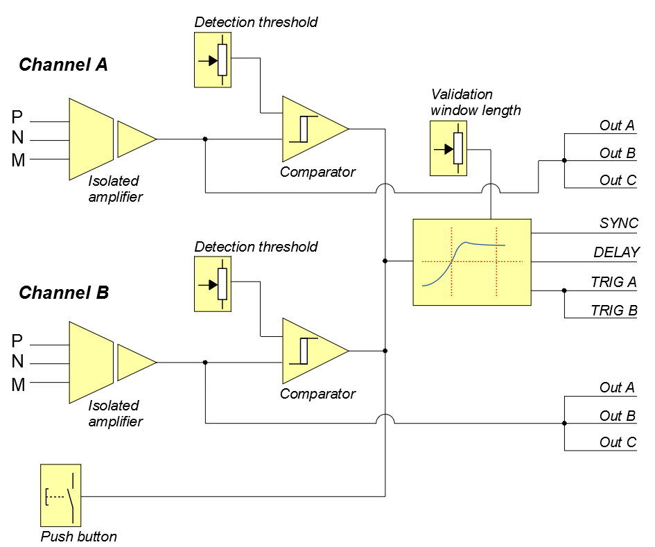
The two channels have independent amplifiers and thresholds, but they share one validation window and one trigger. This is why it is good practice to put signals of the same type on the same card (for example the two current leads, or two halves of the same coil): the validation time and the triggering behaviour can then be tailored to both channels at once.
Input signal: Mono and Differential mode
Each channel has three inputs: positive (P), negative (N) and middle (M). The card can work in two modes, selected channel by channel with a small switch on the PCB (Mono/Diff, see Figure 12).
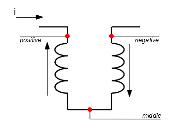
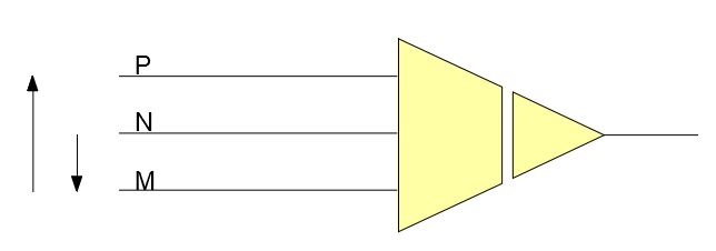
Differential mode. The three wires are used. The card must be connected to the Vtaps so that the voltage levels follow each other as positive, middle, negative (Figures 7 and 8). The card combines the two half-voltages (positive–middle and middle–negative) so that their difference is amplified:
The two halves of a coil see the same inductive voltage when the current changes ( each). In the difference this common-mode component cancels out, and only the differential component is left: quench, flux jumps, vibrations, etc. This is why the differential mode is preferred for quench detection whenever a middle point is available.
Mono mode. Only one voltage is measured, between the positive and the middle inputs. The negative input of the card is not connected. This is also why, during the calibration, one wire per channel can be left open when the card is in mono
Middle point and choice of the mode
A middle point is always desirable for quench detection, and the designer should foresee the VTs accordingly. Without it, the magnet can only be protected in mono mode on its total voltage. In the MCBRD tested at SM18, for example, there was no middle point, and the magnet was protected with the uQDS instead of the PotAims.
Why detection is slower in mono mode
At SM18 it was pointed out that in mono mode, on the total voltage, the quench is detected more slowly than in differential mode.
The voltage across the magnet terminals is:
where is the resistance of the quenched zone. When the quench starts, grows. The power converter, however, cannot react instantly, so in the first milliseconds the current starts to decrease: becomes negative. The inductive term then becomes negative and partly compensates the growing resistive term, and the total voltage stays nearly constant for the first few milliseconds (2–3 ms according to the notes). The quench is there, but it is hidden in the total voltage.
In differential mode the two halves see the same inductive voltage, which cancels, while the resistive voltage appears only in the half that quenched. The difference therefore shows directly, from the very beginning.
Signal pull-up (fail-safe inputs)
The inputs are connected to the isolated power supplies of the input side: positive and negative to the positive rail, middle to the negative rail. If an input is left disconnected or a wire breaks, the input is pulled to the supply and creates a detection event, which triggers the protection system. As for the Safety Matrix outputs, a wiring fault produces the same effect as a real quench.
Amplifier stage
Gains
Each channel has an independently selectable gain: ×1.2, ×4, ×10 or ×40. In addition, each channel has a low gain mode (÷100), used to record high voltage signals, which can be combined with any gain and any mode. In total there are 8 combinations per channel.
Differential mode halves the gain
In differential mode the nominal gains are divided by two. If ×1.2 is selected in differential mode, the actual amplification is 0.6.
The output of the card is limited to ±10 V: beyond that, it saturates. The table below gives the actual gain and the largest input voltage that can be measured without saturation for every combination.
Table 2: Actual gain and maximum input voltage before saturation (±10 V output).
| Nominal gain | Mono | Mono ÷100 | Diff | Diff ÷100 |
|---|---|---|---|---|
| ×1.2 | 1.2 → ±8.3 V | 0.012 → ±833 V | 0.6 → ±16.7 V | 0.006 → ±1667 V |
| ×4 | 4 → ±2.5 V | 0.04 → ±250 V | 2 → ±5 V | 0.02 → ±500 V |
| ×10 | 10 → ±1 V | 0.1 → ±100 V | 5 → ±2 V | 0.05 → ±200 V |
| ×40 | 40 → ±0.25 V | 0.4 → ±25 V | 20 → ±0.5 V | 0.2 → ±50 V |
The values in the ÷100 columns above 1 kV are only theoretical: the isolation of the card is specified for “over 1 kV”.
How the gain is selected.
- The gain is chosen with a selector switch on the PCB of each channel, so the card must be extracted from the crate.
- Only one gain per channel must be selected. If more than one is selected, the card does not work properly.
- The ÷100 mode is activated with a small switch on the PCB of each channel.
- On the front panel, the gain indicator LEDs show the selected gain and a separate LED shows whether ÷100 is active.
Use the highest gain that does not saturate
Jean Luc pointed out, looking at the schematic of the card, that the comparator works better with higher amplitude signals. When possible, choose the highest gain that keeps the expected signal within ±10 V.
Offset and balancing
- Offset. Each channel has an offset potentiometer to bring to zero any offset voltage generated in the setup. It is adjusted with a screwdriver on the front panel, monitoring the output.
- Balancing (équilibrage). Meaningful only in differential mode. With the balancing potentiometer the amplification of the two halves can be made slightly different, to compensate differences in connection resistances etc., and bring the balanced signal to zero. Changing it slightly changes the input resistance in both modes.
The differential measurement is described by:
where is the gain, and the two half-signals and the balancing factor.
Input impedance
The input impedance depends mainly on the ÷100 and Mono/Diff settings; the effect of the balancing is negligible. The values measured by CERN (resistive part only) are:
Table 3: Measured input resistance of a PotAim channel.
| Setting | Pos – Neg | Pos – Mid | Neg – Mid |
|---|---|---|---|
| Diff, not ÷100 | ~1 MΩ | ~30 MΩ | ~30 MΩ |
| Diff, ÷100 | ~1 MΩ | ~500 kΩ | ~500 kΩ |
| Mono, not ÷100 | Open circuit | ~30 MΩ | Open circuit |
| Mono, ÷100 | Open circuit | ~400 kΩ | Open circuit |
Card configuration and front panel
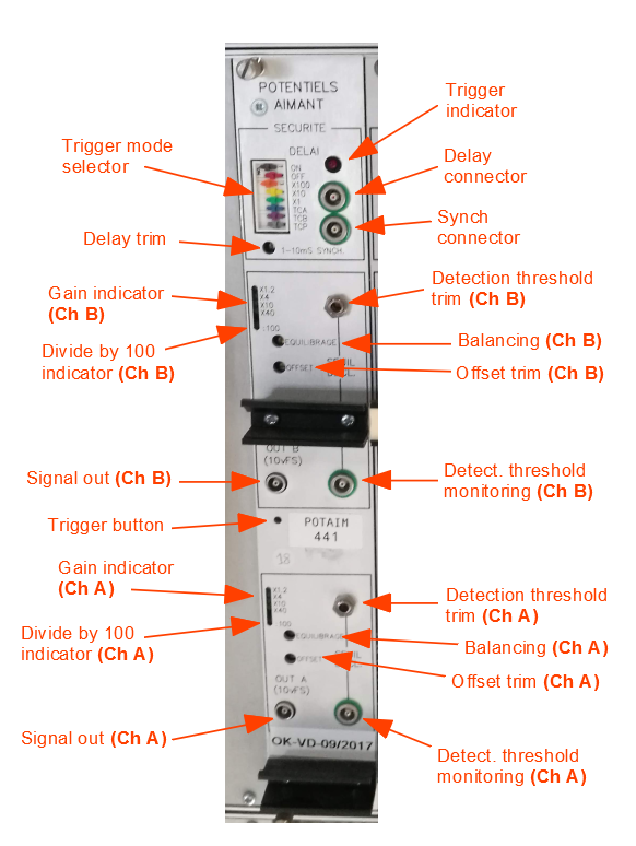
The settings made on the PCB (card extracted from the crate) are shown in Figure 10, the controls on the front panel in Figure 11.
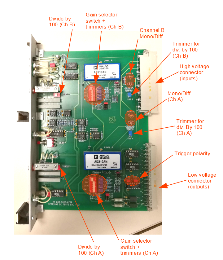
On the PCB:
- Mono/Diff switch, one per channel;
- gain selector switch and trimmers, one per channel;
- ÷100 switch and its trimmer, one per channel;
- trigger polarity jumpers.
On the front panel:
- Trigger mode selector (see below);
- Trigger indicator LED;
- Delay trim, to adjust the validation time with a screwdriver;
- DELAY and SYNCH connectors, giving the two internal signals of the trigger mechanism;
- for each channel: gain indicator LEDs, ÷100 indicator, detection threshold trim, threshold monitoring output, offset trim, balancing trim and signal output;
- trigger button, to trigger the card manually and test the signal going to the Safety Matrix.
Trigger mode selector
The trigger mode selector is a block of eight small switches (Figure 13).
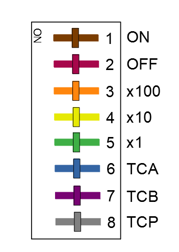
Table 4: Switches of the trigger mode selector.
| # | Label | Function |
|---|---|---|
| 1 | ON | Enables triggering with validation window. |
| 2 | OFF | Enables triggering without validation window (immediate trigger). |
| 3 | x100 (orange) | Longest timescale of the validation window: 100 ms – 1 s. |
| 4 | x10 (yellow) | Middle timescale: 10 – 100 ms. |
| 5 | x1 (green) | Shortest timescale: 1 – 10 ms. |
| 6 | TCA | Selects the trigger line of channel A to be tested with the push button. |
| 7 | TCB | Selects the trigger line of channel B to be tested with the push button. |
| 8 | TCP | Selects the polarity (positive or negative) of the test signal generated by the push button. |
- Only one timescale (x100, x10 or x1) must be selected. Within the chosen range, the exact validation time is set with the delay trim. The validation time is normally given by the test engineer in the test plan.
- TCA, TCB and TCP are only used to test the card (see the trigger check in Calibration of the PotAim card with crate). TCA and TCB must never be ON at the same time.
Exactly one of ON or OFF
Before the test, make sure that exactly one of the ON and OFF switches is enabled. If neither is enabled, the card will not trigger; if both are enabled, the behaviour can be unstable. In normal operation the validation window is used, so ON is enabled and OFF is disabled.
Threshold
The threshold of each channel is set with the detection threshold trim, using a screwdriver, and can be monitored on the threshold monitoring output with an oscilloscope or a multimeter. The threshold acts on the amplified signal, so it is linked to the gain:
For example, 70 mV with gain 40 gives 2.8 V displayed. If the gain is changed, the threshold must be changed accordingly.
Triggering mechanism
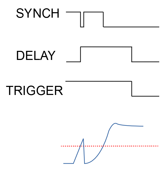
The trigger is generated from two internal signals, available on the front panel connectors SYNCH and DELAY. The trigger signal itself is only available on the low voltage back-plane connector (and from there on the digital outputs of the crate).
- SYNCH goes low when the input signal exceeds the threshold.
- DELAY is the validation window, which starts at the same moment.
- The trigger is generated only if both SYNCH and DELAY are low, i.e. if the signal is still above the threshold at the end of the validation window.
- The trigger resets when the signal goes back below the threshold.
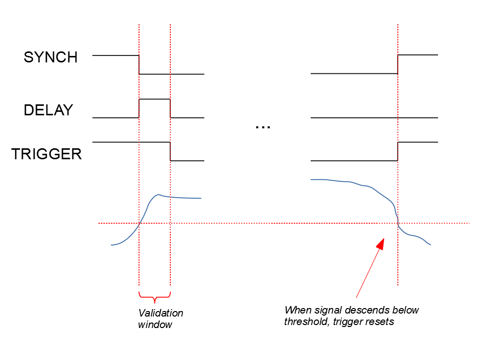
Two particular cases are shown in Figure 15:
- if SYNCH disappears within the validation window (a short spike), there is no trigger;
- if SYNCH disappears and reappears within the validation window and then stays, the trigger appears only at the end of the second validation window.
Triggering without validation window is also possible, by disabling ON and enabling OFF.
Output signals
- Trigger. A 15 V push-pull signal. It is duplicated (Trig out 1 and Trig out 2), and the polarity of each output can be set by a jumper. The trigger stays active as long as the input signal is outside the threshold levels. The PotAim outputs are active low, which is why they must not be inverted by the InterADA cards of the Safety Matrix.
- Isolated analog signal. The output of the amplifier stage, i.e. the same signal fed to the comparators. It is triplicated and placed on separate crate connectors (analog outputs A, B and C). It is limited to ±10 V.
Back-plane connectors
Each card has two back-plane connectors: a high voltage connector for the input signals (directly connected to the Vtaps or to other crates) and an isolated low voltage connector for the outputs and the power supply.
Table 5: High voltage connector.
| Pin | Signal | Pin | Signal |
|---|---|---|---|
| D6 | NC | Z4 | Channel A Positive |
| D10 | NC | Z8 | Channel A Negative |
| D14 | NC | Z12 | Channel A Middle |
| D18 | NC | Z16 | NC |
| D22 | Channel B Positive | Z20 | NC |
| D26 | Channel B Negative | Z24 | NC |
| D30 | Channel B Middle | Z28 | NC |
| Z32 | NC |
Table 6: Low voltage connector (rows A and C carry the same signals).
| Pin (A / C) | Signal |
|---|---|
| 2 | Channel A analog out |
| 4 | Channel A analog out |
| 6 | Channel B analog out |
| 8 | Channel B analog out |
| 10 | Channel A analog out |
| 12 | Channel B analog out |
| 14, 16, 18 | NC |
| 20 | Trig out 2 |
| 22 | Trig out 1 |
| 24, 26 | NC |
| 28 | −15 V |
| 30 | +15 V |
| 32 | GND |
NC = not connected. These are the same pins used in Calibration of the PotAim card with crate: inputs Z4–Z12 and D22–D30 for the gain calibration, C28, C30 and C32 for the check of the ±15 V supply.
Setting the PotAim for Different Signals
The mode, gain, threshold and validation time depend on the signal the card is protecting. The guidelines below were given by Jérôme and Jean Luc at SM18; the actual values must always come from the test plan.
Table 7: Typical settings at SM18.
| Signal | Mode | Nominal gain (actual) | Validation time | Threshold |
|---|---|---|---|---|
| Splices | Mono | ×40 (40) | 5–8 ms | ~10 mV |
| Magnet, with middle point | Diff | ×10 (5) | ~10 ms (NbTi up to 20 ms; HTS ~10 ms) | Depends on the conductor (e.g. 3 mV for HTS) |
| Magnet, total voltage (no middle point) | Mono | ×1.2 (1.2) | ~10 ms | 2–3 × (typically ~25 mV) |
| Current leads (copper part) | Mono | ×40 (40) | ~500 ms | 70–100 mV |
| Total voltage for recording the extraction | Mono | low gain with ÷100 | — | — (no protection role) |
Splices
A splice has almost zero resistance and no inductive pick-up, so its signal is very small and a quench must be detected very fast. A high gain (×40) is used, in mono (direct) mode, with a validation time between 5 and 8 ms and a threshold of about 10 mV. The values depend on the type of splice (NbTi, soldered, etc.).
Magnet protection with a middle point (differential)
When a middle point is available, the differential mode is used with gain ×10, i.e. an actual gain of 5. The validation time and threshold depend on the conductor:
- HTS: the quench propagates slowly, and by the time it is visible it may already be late, so a low threshold and a short time are used, e.g. 3 mV and 10 ms;
- NbTi: the validation time can be increased up to about 20 ms.
Magnet protection on the total voltage (mono)
Without a middle point, the magnet is protected in mono mode on the total voltage, with a low gain (×1.2), since the inductive voltage during the ramps is included in the measured signal. The validation time is typically about 10 ms.
The threshold is set from the inductive voltage expected during the ramp: knowing the inductance of the magnet and the ramp rate, compute and set the threshold at 2–3 times this value, typically around 25 mV. The resistive component is not added in this calculation, because in normal operation (detection) the magnet is not quenching.
Spurious triggers at the startup of the power converter
When the power converter is switched on, it is not yet in closed-loop regulation. While it brings the current to the minimum current required before ramping (about 200 A in the 20 kA station, as far as remembered), the voltage picked up can exceed the threshold, leading to frequent spurious triggers.
The workaround used at SM18, not written in the procedures, is:
- disable the PotAim card protecting the total voltage;
- switch on the power converter and reach the minimum current;
- enable the same PotAim card again;
- start the ramp.
This avoids the improper trigger that would bring the system back to IDLE. The problem does not occur in differential mode, where the inductive voltage cancels out. The workaround leaves the magnet without this protection for a short time, so it must be applied consciously.
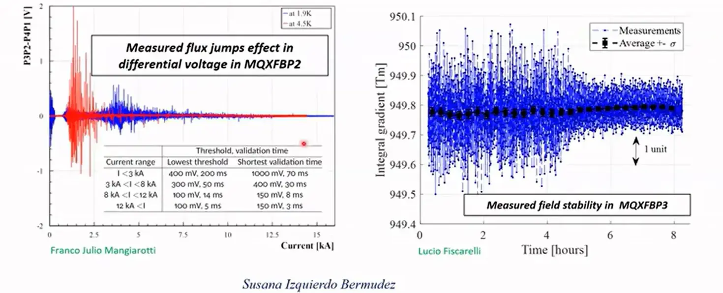
CERN has also developed more advanced PotAim cards with multiple thresholds, one for low current and one for high current. They were introduced because Nb₃Sn magnets show many voltage spikes at low current: with a single threshold, every spike was seen as a quench and the magnet was hard to protect. According to Jérôme, FREIA should have one or two of these cards.
Current leads
For the current leads, only the copper part is protected, in mono mode, with a high gain (×40). Typical values are a threshold of 70–100 mV and a validation time of 500 ms.
The protection of the current leads is critical: they must be operated at the proper temperature. The copper bar is gas cooled and, at the same time, equipped with heaters, so that it works at a stable temperature. The threshold depends on the current flowing in the magnet and on the resistance of the copper bar: for the same lead, the higher the current, the higher the voltage and the threshold to be set. The correct threshold for the leads should be given by their manufacturer.
Recording the extraction on the total voltage
When there is no middle point and the magnet is protected on the Vtaps of the current leads (the total voltage, called Vsum or Vtot), Jérôme recommends routing this signal to two PotAim cards:
- one with high gain, to see the quench appear;
- one with very low gain (÷100 mode), to record a non-saturated signal during the fast discharge (energy extraction).
During the extraction, the voltage across the magnet terminals equals the voltage across the dump resistor, , and can reach about 200 V. Inside the magnet this voltage is sustained mainly by the inductive voltage , since the magnet is discharging on the dump resistor. With gain 1.2 in mono, 200 V would give 240 V at the output, far beyond saturation; with gain 1.2 ÷100 (0.012) it gives 2.4 V, well within ±10 V (see Table 2).
This second card is used only to observe the extraction after the quench, not for protection.
Choosing the validation time
The validation time adds directly to the time during which the quench develops at full current, so it must be compatible with the MIITs of the magnet. The MIITs are the integral from the start of the quench to the end of the discharge. Roughly, they are the sum of:
- the time before the extraction (detection, validation, Safety Matrix delay, switch opening), at nearly full current: ;
- the exponential discharge on the dump resistor, with time constant : about .
The total must stay below the value that keeps the hot-spot temperature of the conductor safe. The validation times are normally given by the test engineer in the test plan.
Feedback
Found an error or something outdated in this note? Please contact Davide Cuneo (davide.cuneo@physics.uu.se).