Document information
Tags/Project: Equipment-wiki
| Metadata Field | Document Information |
|---|---|
| Status | Under Review |
| Created | 2026-06-24 |
| Last Updated | 2026-09-29 |
| Author | Davide Cuneo |
| Rev. # | 1.3 |
| Reviewers | Davide |
About the document
This document provides a description of the control systems across the facility and process instrumentation.
PLC
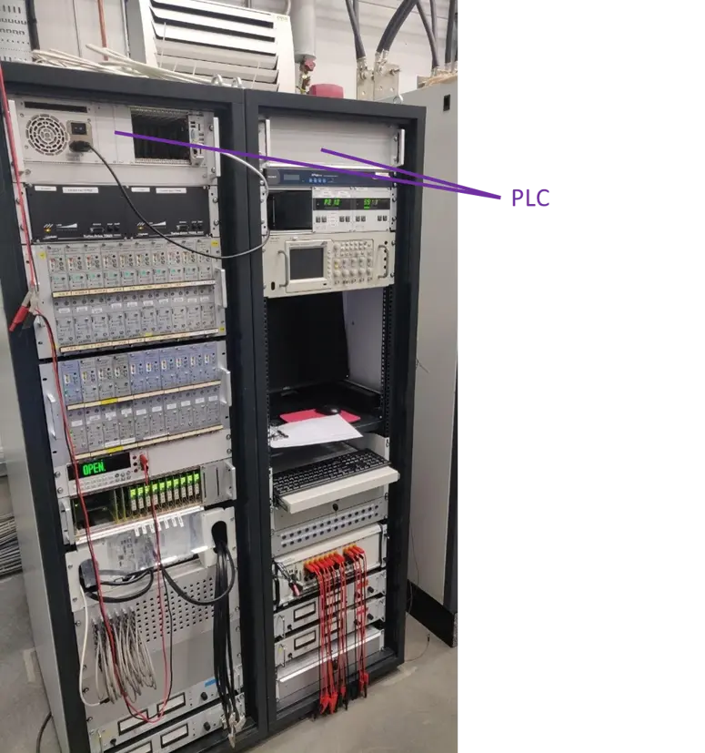
Automation, data acquisition, and real-time process loops across the GERSEMI facility are managed by an industrial Programmable Logic Controller (PLC) architecture utilizing Siemens S7-300 hardware controllers. The physical control hardware, including the PLCs, circuit breakers, and system power supplies, is housed within electrical cabinets situated adjacent to the vertical cryostat pit. To facilitate rapid commissioning and hardware modifications during insert transitions, all field cabling is routed through standardized plugs and connectors terminating at localized general electrical distribution boxes.
The physical PLC layer interfaces with the distributed field sensors and analog current-driven actuators via Profibus or Ethernet communication networks. For system commissioning and initial diagnostic runs, the PLC layer is integrated with a Supervisory Control and Data Acquisition (SCADA) system operating on a WinCC interface, which maps and handles all digital and analog I/O procedures to provide the real-time dynamic data required for plant supervision. THE PLC features 32 digital inputs and 32 outputs, plus 6 analog inputs (ethernet) and 11 digital inputs (ethernet).
During standard experimental operations with the GERSEMI cryostat, the entire data architecture and control sequences run under the Experimental Physics and Industrial Control System (EPICS) framework, allowing for synchronous online diagnostics and comprehensive post-run data logging.
Process Instrumentation and Sensor Allocation
The underlying control loops utilize distinct sensor technologies specifically selected to match the process fluid characteristics and the active thermal regime being monitored. For the liquid nitrogen circuits and equipment shield boundaries, temperature monitoring is handled by PT100s, utilizing both thin-film and wire-wound configurations wired directly to the analog input cards of the Siemens PLC. Conversely, the low-temperature lines operating with liquid, sub-cooled, or supercritical helium are mapped via calibrated Cernox thermometers (CX1050SD). These cryogenic sensors interface with a dedicated CABTF controller containing 16 inlets, which multiplexes the inputs from up to 48 distinct Cernox channels before routing the processed variables directly to the central automation layer.
Liquid helium level measurements inside the vessels are tracked via superconducting level probes distributed across four key nodes depending on the active test configuration. The tracking array allocates one baseline probe inside the primary valve box volume and one baseline probe dedicated to the internal 4 K buffer tank. When configuring the cryostat for cavity tests, two probes are connected in series within the “Liquid Insert” assembly, whereas magnet test runs utilize four independent probes arranged within the “Magnet Insert” to map the three separate helium baths, with two of these sensors linked in series to simulate a single extended probe geometry.
Mass flowmeters are installed on both the liquid nitrogen exhaust lines and the helium gas return lines, delivering real-time flow data used by the control software to calculate the static and dynamic thermal losses across each active cryogenic circuit. Finally, pressure regulation within the critical 4 K buffer and 2 K sub-cooling vessel spaces is achieved through room-temperature VAT butterfly valves. Each modulating valve is regulated by dedicated proportional–integral–derivative (PID) software loops executing cyclically within the PLC program, which continuously process sub-atmospheric pressure feedback from capacitive sensors to maintain tight pressure stability in the helium baths.
Feedback
Found an error or something outdated in this note? Please contact Davide Cuneo (davide.cuneo@physics.uu.se).