Document information
Tags/Project: Equipment-wiki
| Metadata Field | Document Information |
|---|---|
| Status | Under Review |
| Created | 2026-06-24 |
| Last Updated | 2026-09-29 |
| Author | Davide Cuneo |
| Rev. # | 1.3 |
| Reviewers | Davide |
About the document
This document provides a description of the equipment and GERSEMI (magnet insert) associated instrumentation to test magnets.
Magnet Powering
The superconducting magnet insert is powered via the CERN-developed COMBO (COmmercial Based cOnverter) system, a rack architecture composed exclusively of commercial off-the-shelf units designed to replicate standard accelerator power supply functionalities. The facility integrates two independent 2 kA DC power converters operating at a maximum output voltage of 10 VDC. The power network features a total circuit resistance of 80 m and is managed through a CERN FGC3 high-level digital controller executing a high-precision digital current loop based on feedback from high-precision DC Current Transformers (DCCTs). The FGC3 controller acts as the central diagnostic node, collecting and reporting system statuses, interlock faults, and real-time current measurements to remote supervision services. The power converters support ramping rates up to 20 A/s.
The baseline COMBO power supply units are inherently unipolar, operating strictly as a 1-Quadrant system providing positive voltage and current (+V, +I). To enable multi-quadrant testing, advanced forward/reverse magnetic field mapping, and automated hysteresis loop profiling without manual cable decoupling, an automated high-current mechanical polarity reversing switch managed directly by the facility PLC is integrated into the rack. This hardware layout allows the system to navigate across four operational quadrants through the following transitions, requiring the current to always cross zero before triggering a polarity flip. To change the operative quadrant power must be shut off.
INFO
Quadrant 1 (+V, +I): Standard forward powering mode where the power supply actively delivers energy to the inductive load.
Quadrant 3 (-V, -I): Reversed powering mode. The current is brought to zero, the mechanical polarity switch inverts the DC distribution bar lines, and the converters resume power delivery under a negative voltage and current profile.
Quadrant 2 (+V, -I): Current reduction mode from a reversed state. To drive the negative current back to zero, the loop voltage must transition to positive. This reversal is driven naturally by the magnet’s self-inductance, which generates a counter-electromotive force (induced voltage) opposing the decrease in current, inherently forcing the system into Quadrant 2.
Quadrant 4 (-V, +I): Energy extraction mode. The primary power supply lines are completely bypassed, and the dedicated Energy Extraction Unit is engaged to absorb the stored magnetic energy and dump it into external resistors.
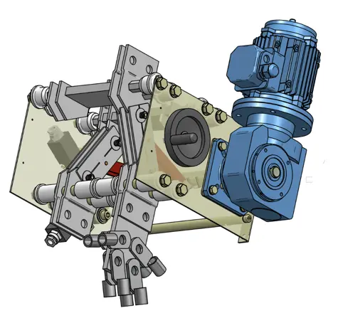
Energy Extraction Units and Dump Resistor Matrix
To protect the superconducting magnet under test from irreversible damage during a quench, the facility integrates two independent water-cooled Energy Extraction Units (one configured for each 2 kA DC line). Designed by CERN, each unit utilizes solid-state Insulated-Gate Bipolar Transistor (IGBT) switches arranged in a fully laminated busbar structure to minimize stray inductances and optimize the sizing of the internal compensating capacitances.
The hardware layout of each extraction unit features two identical IGBTs connected in series for redundancy, coupled with a series-connected reverse-blocking power diode. The semiconductors are mounted on three dedicated water-cooled heat sinks. Although the IGBTs are rated for a maximum nominal current of 3.6 kA, they are operated up to a maximum of 1 kA DC; this structural derating eliminates the need for active water cooling on the main emitter and collector copper busbars. Heavy-duty 1 kA electrical connections between the basic pluggable modules and the main DC distribution bars at the rear of the instrumentation rack are maintained via spring-loaded fork connectors embedded with multi-lam strips of Copper-Beryllium (CuBe) louvers.
The extraction units are tied to a modular dump resistor matrix configured to dissipate the stored magnetic energy (rated up to a 350 kJ structural extraction limit) outside the liquid helium bath. The matrix consists of resistor units for each of the following nominal values:
- 2x 300 m units
- 4x 600 m units
- 5x 700 m units
By altering the physical series or parallel coupling configurations of these elements, operators can select a wide array of total dump resistance values ranging from a minimum of 77 m up to a maximum of 3200 m, customizing the discharge time constant () to match the inductance of the specific magnet under test.
Data Acquisition
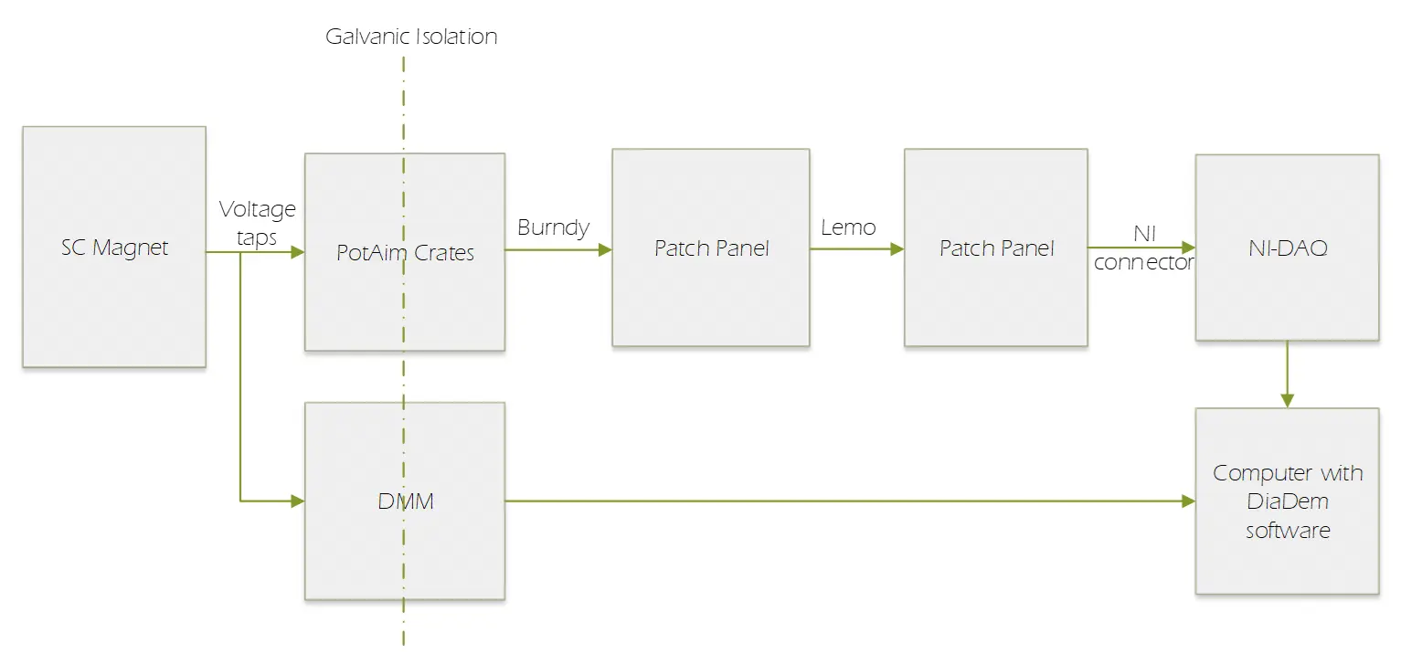
Diagnostic monitoring of the insert and magnet terminals is split between two National Instruments (NI) hardware architectures operating with unrestricted acquisition time windows, namely DAQ and DMM. Fig. 1 shows the logic of the signals to be acquired and used for the various operations.
DAQ
Transient voltage signals across the coil windings and critical joint interfaces are captured using a high-speed National Instruments PXI Express (PXIe) instrumentation architecture operating analogous to a digital storage oscilloscope.
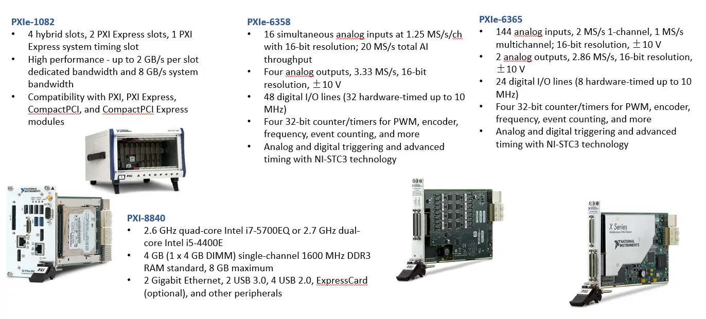
The physical system is housed within a rugged PXIe-1082 hybrid chassis, which provides a dedicated backplane bandwidth of up to 2 GB/s per slot (8 GB/s total system bandwidth) and distributes synchronous hardware timing and advanced analog/digital triggering signals across the backplane slots via integrated NI-STC3 technology.
Data streaming, localized calibration, and industrial network communication with the laboratory-wide EPICS framework are managed by a PXI-8840 embedded controller installed in the dedicated system slot. This module utilizes a 2.6 GHz quad-core Intel i7-5700EQ processor paired with an 8 GB DDR3 RAM architecture to handle high-throughput DMA (Direct Memory Access) data transfers directly from the acquisition modules, eliminating software processing bottlenecks and enabling continuous, unrestricted runtime execution.
The DAQ framework splits diagnostic monitoring into two distinct hardware-mapped acquisition tiers.
High-frequency transient capture is dedicated to recording the rapid electrical onset of the quench barrier across a narrow 45-millisecond window. This high-speed tier supports up to 64 independent channels sampling at rates scaling up to 2 MSa/s with a 16-bit resolution. Physically, this infrastructure is achieved by networking a cluster of three PXIe-6358 multifunction data acquisition modules in parallel. Each PXIe-6358 card contributes 16 simultaneous-sampling analog inputs rated at 1.25 MSa/s per channel, establishing an aggregate single-board throughput of 20 MSa/s that completely eliminates inter-channel phase delays when capturing sharp voltage spikes. The module also provisions four analog outputs operating up to 3.33 MS/s and 48 digital I/O lines to facilitate auxiliary hardware-timed triggering up to 10 MHz.
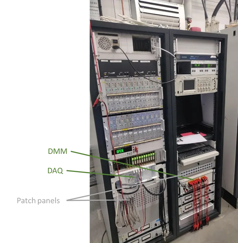
Concurrently, low-frequency continuous monitoring is available but most likely not used. This is done using a PXIe-6365 card which monitors up to 72 independent voltage channels with a continuous sampling frequency of 1 kSa/s at 16-bit resolution. For specific single-channel diagnostic calibration runs, the card can scale its input sampling up to 2 MS/s, while providing two 16-bit analog outputs operating at 2.86 MS/s, 24 digital I/O lines hardware-timed up to 10 MHz, and four 32-bit counter/timer channels configured for advanced pulse-width modulation, event counting, and encoder tracking. The four compenents described above are shown in Fig. 2.
Digital Multimeter (DMM)
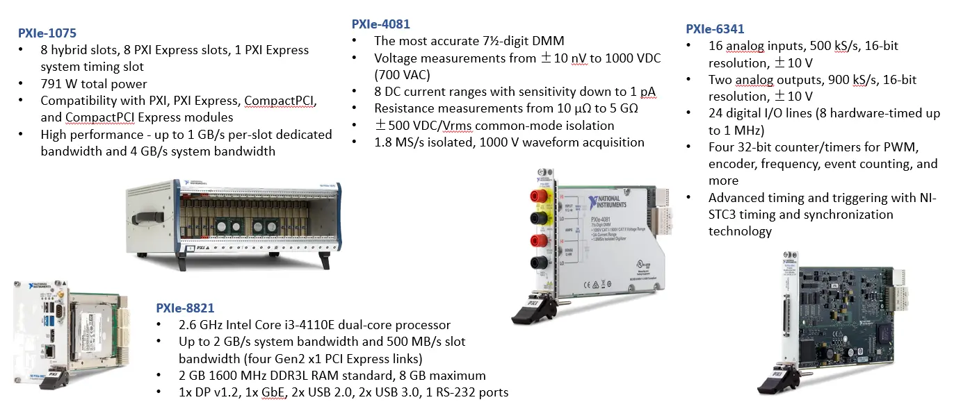
For continuous live monitoring of steady-state parameters requiring low resolution, specifically Residual Resistivity Ratio (RRR) profiling, splice contact resistance monitoring, and inductance evaluations, the facility deploys a secondary dedicated National Instruments instrumentation station operating analogous to a high-precision voltmeter. This sub-system is physically segregated from the primary transient DAQ and is housed within a National Instruments PXIe-1075 chassis. The mechanical backplane of this containment unit features 8 hybrid slots, 8 PXI Express slots, and 1 PXI Express system timing slot, operating with a total power rating of 791 W.
System execution, data sorting, and laboratory network synchronization are controlled by a PXIe-8821 embedded controller situated in the main system slot. This controller architecture is driven by a 2.6 GHz Intel Core i3-4110E dual-core processor, utilizing a baseline memory profile of 2 GB of 1600 MHz DDR3L RAM (expandable up to 8 GB) to maintain a system bandwidth of up to 2 GB/s alongside a dedicated per-slot bandwidth of 500 MB/s over four Generation 2 x1 PCI Express links. The physical faceplate of the controller handles connectivity through individual DisplayPort v1.2, Gigabit Ethernet, RS-232 serial interfaces, alongside two USB 2.0 and two USB 3.0 peripheral ports.
The measurement capability of this station relies on the co-axial integration of a high-accuracy digitizing multimeter module and a multi-channel analog data acquisition card sharing the PXIe-1075 backplane bus. A PXIe-4081 digital multimeter module provides a measurement accuracy of digits. The internal ADC architecture of the PXIe-4081 enables steady-state VDC tracking across a broad input scale stretching from up to 1000 VDC (and up to 700 VAC), while offering an isolated waveform acquisition rate of 1.8 MS/s under a structural common-mode isolation boundary of . The module also provisions 8 distinct DC current ranges featuring an absolute resolution sensitivity scaling down to 1 pA, alongside direct resistance measurement capabilities covering a span from 10 up to 5 G.
To support multi-channel operations across the test bench without restricting the continuous acquisition software window, the high-resolution DMM channel is mapped alongside a PXIe-6341 X Series multifunction data acquisition module. This card accommodates up to 10 independent signal lines across its 16 available analog input channels, which operate with a 16-bit resolution at a aggregate multiplexed sampling speed of 500 kS/s across a nominal input boundary. Synchronization and trigger distribution between the single-channel PXIe-4081 DMM and the multi-channel PXIe-6341 inputs are maintained via integrated NI-STC3 timing technology. The PXIe-6341 module further complements the testing station by provisioning two 16-bit analog outputs operating at 900 kS/s, 24 digital I/O lines hardware-timed up to 1 MHz, and four 32-bit counter/timer circuits configured for pulse-width modulation, encoder tracking, and advanced frequency event counting. The four compenents described above are shown in Fig. 3.
Quench Detection and Safety Matrix Logic
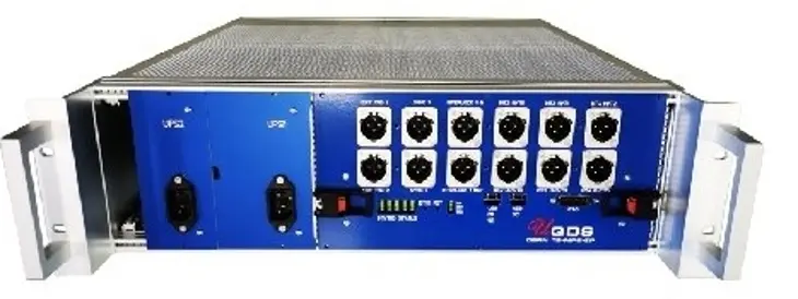
The core hardware safety layer configured to protect the magnet is an automated system consisting of the Universal Quench Detection System (uQDS), a hardware trigger matrix, localized isolation cards, and a safety PLC.
Voltage Taps (VTs) and PotAim Isolation Modules
The primary diagnostic inputs are miniature wire voltage taps (VTs) soldered directly onto distinct segments of the superconducting coils, the current leads, and the superconducting cable splices. A total of 32 VTs channels are routed through the top flange to map the magnet profile, with a critical baseline of 8 VTs positioned symmetrically above and below the lambda plate to track the current lead-to-SC cable and SC cable-to-magnet joint interfaces. By measuring the differential voltage across two adjacent VTs or a three-tap balance network, the system detects the onset of resistivity () signaling a local transition from superconducting to normal states.
VTs terminate directly at PotAim (Potential Amplifier and Isolation) modules before routing to the digital DAQ. The facility integrates 20 PotAim cards, which execute the following safety and conditioning functions:
- Galvanic Isolation: The cards act as a heavy safety barrier, providing complete galvanic isolation to absorb severe inductive voltage spikes generated during a rapid magnet discharge, preventing downstream destruction of the DAQ electronics.
- Signal Amplification: The low-voltage analog signals from the V-taps are amplified to optimize resolution across the monitoring system.
- Hardware Validation: Each PotAim module is configured with a fixed, hardwired voltage threshold and an independent validation time constant. If a differential voltage signal exceeds the voltage threshold for a duration longer than the defined validation time, the card validates the quench and outputs a hardware trigger.
The Trigger Matrix and Safety PLC Interlocks
The validated quench signal from the PotAim cards is routed directly to a centralized hardware Matrix system. The Matrix instantly duplicates and distributes the trigger signal across all auxiliary plant subsystems to initiate a synchronous safety shutdown sequence:
- Shutdown of the Power Converter: Terminates the primary COMBO power supply output.
- Energy Extraction: Triggers the IGBT switches to open, forcing the current through the external dump resistor matrix to dissipate the magnetic energy outside the liquid helium environment.
- Data acquisition: Triggers the high-speed LF and HF DAQ cards to freeze their respective 1.2 s and 45 ms data windows for post-quench root-cause analysis.
- Alignment with the cryogenic system: Signals the facility safety PLC to align the cryostat valves for pressure mitigation.
The safety PLC functions as the overall supervisory logic layer of the quench system. It continuously cross-checks that all post-trigger conditions from the satellite equipment are satisfied. During the initial startup phase, the PLC scans the status of the entire satellite network alongside cryogenic variables (such as helium bath pressures and levels); if any connected component reports an anomalous condition or a fault, the PLC flags an interlock state and blocks the FGC3 controller from activating the main power converters.
High-Voltage test and continuity
The facility is equipped to run High-Voltage (HV) tests to monitor shorts on the designated device. It comes with an high voltage tester, a DC power supply for continuity test and a signal generator used to calibrate the PotAim cards.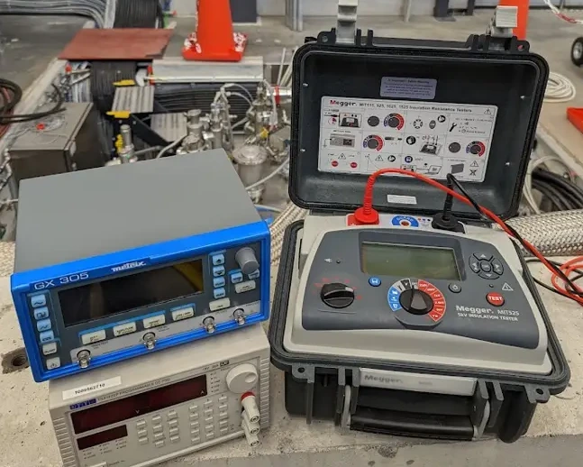
Other Instrumentation and Magnetic Measurements
The top flange integration is completed by secondary diagnostic channels and provisions for magnetic field characterization:
-
Distributed Temperature Channels: Cryogenic instrumentation lines are mapped across the top plate to interface with internal sensor arrays distributed along the vertical axis of the insert structure. These include Cernox resistance thermometers (CX1050SD) multiplexed through the CABTF controller, thermocouples, and platinum resistance thermometers (Pt100) to track liquid helium head profiles, monitor vertical thermal gradients during cool-down sequences, and verify shield thermalization.
-
Magnetic Measurement Anticryostat: The top flange assembly can be modified to accommodate a specialized anticryostat insert. This structure provides a dedicated isolated warm volume (maintained at room temperature) extending down into the core of the cold vessel. This warm bore allows the insertion of a rotating measurement coil to perform high-precision magnetic field profiling. Under this configuration, the facility can test magnet structures up to a maximum length of 2.2 m, featuring a maximum internal aperture diameter of 50 mm, across a sensible magnetic measurement field area of 500 mm.
Feedback
Found an error or something outdated in this note? Please contact Davide Cuneo (davide.cuneo@physics.uu.se).